Date: 4 - 8 November 2013
Subject : 1) Research about the Light Emitting Diodes (LED) used in Smart Grass Cutter technology and also designing a illustration for the prototype.
Introduction:
The purpose of this task is to continue a research about above mention components that will be used in this project. The research include the input voltage and current for the LED.
The purpose of this task is to continue a research about above mention components that will be used in this project. The research include the input voltage and current for the LED.
Objectives:
- To find the suitable component that will need used in this projects.
- To get the actual design for this prototype.
Project Description:
Information is gathered using resources such as the internet and the books. The other source is from Jalan Pasar which is the place that distributed all electronic and electrical components. Below is the components description.
1) Light Emitting Diodes (LED)
V=IR.
2) Illustration for the prototype of smart grass cutter
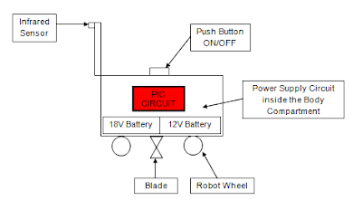
Based on figure 2, it is the design for the prototype of smart grass cutter. It can see each compartment used in this robot. All circuits such as power supply, infrared sensor, PCB layout with IC, DC motor drives circuit are put inside the body compartment. the infra red sensor must at the front of the robot because it will detecting any object and send the signal to the controller.
Problem Encountered:
From
this research, I have to create the shape for my prototype. Basically this design is small and all circuit need to put inside the body compartment. If the shape is big then its need more costing to buy the material for the prototype. Therefore this project also can be function even the shape is too small as long the objectives is achieved. However the project is still on
schedule and
will proceed as how the project was planned.
Project Outcome:
More outcome has achieved from this research. Next planning is want to research about the circuit that have to used in Proteus software. Several circuits need to create such as power supply circuit, circuit for DC motor and etc. My research project is on schedule and I should encounter no problems finishing it.
Information is gathered using resources such as the internet and the books. The other source is from Jalan Pasar which is the place that distributed all electronic and electrical components. Below is the components description.
1) Light Emitting Diodes (LED)
A normal LED use 5V and 5mA
to operate and through LED the current status of the system can be known. LED is very sensitive if the current is exceed then 5mA the LED will burn. So its need to put the resistor to the LED for limit the current.
From the data sheet, the voltage for LED is 5v and the maximum current is 5mA. by ohm law, the value of resistor can determine.
V=IR.
Where V=5VDC,
I=5mA
R=1KΩ
LED must be connected the correct way round, the diagram may be labeled
a or + for anode and k or - for cathode (yes, it
really is k, not c, for cathode!).
The cathode is the short lead and there may be
a slight flat on the body of round LED. If you can see inside the LED the
cathode is the larger electrode (but this is not an official identification
method). LED can be damaged by heat when soldering, but the risk is small
unless you are very slow. No special precautions are needed for soldering most
LED.
| Figure 1: Light Emitting Diode |
2) Illustration for the prototype of smart grass cutter
 |
| Figure 2: Design for the Prototype of Smart Grass Cutter |
Based on figure 2, it is the design for the prototype of smart grass cutter. It can see each compartment used in this robot. All circuits such as power supply, infrared sensor, PCB layout with IC, DC motor drives circuit are put inside the body compartment. the infra red sensor must at the front of the robot because it will detecting any object and send the signal to the controller.
Problem Encountered:
Project Outcome:
More outcome has achieved from this research. Next planning is want to research about the circuit that have to used in Proteus software. Several circuits need to create such as power supply circuit, circuit for DC motor and etc. My research project is on schedule and I should encounter no problems finishing it.
No comments:
Post a Comment